Utilized Skills
Task: Create an interface device to detect when a vehicle is running, and then once the vehicle is turned off enable a cooling fan.
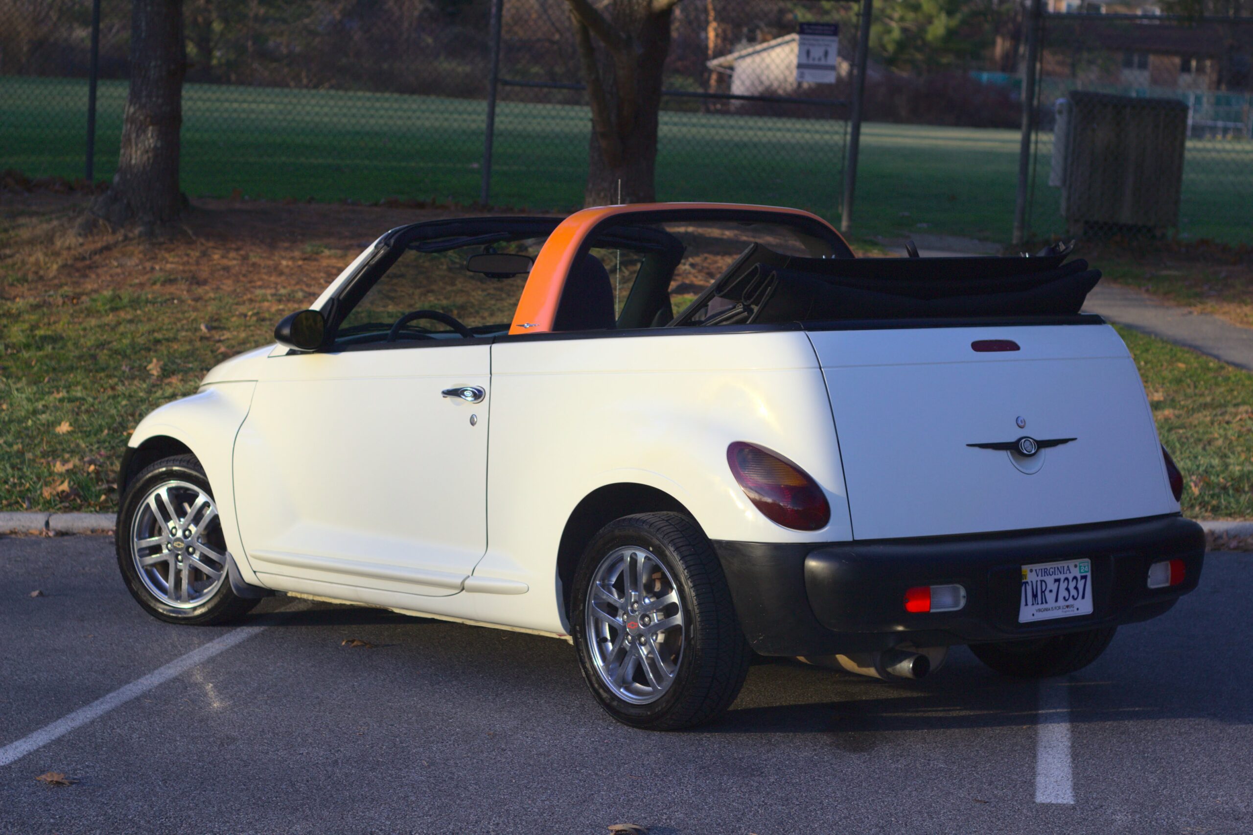
Purpose: Prolong the life of a common failure with the Chrylser PT Cruiser: heat soaking of the engine computer.
Outcome: Successful design with custom PCBs and custom C code.
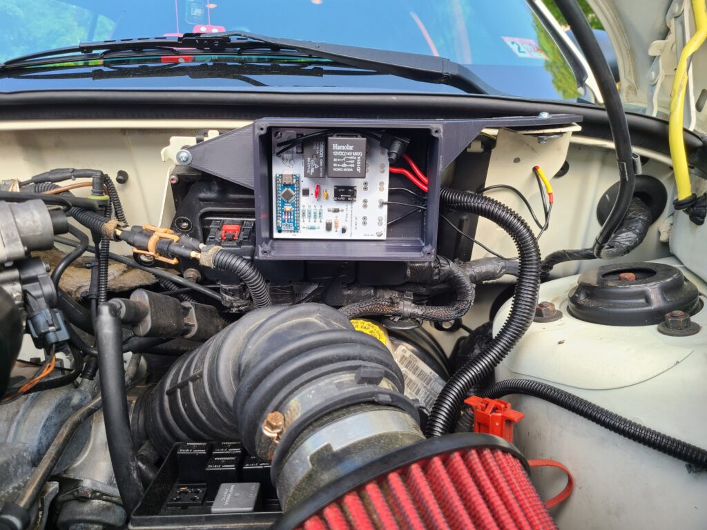
The Design
Hardware
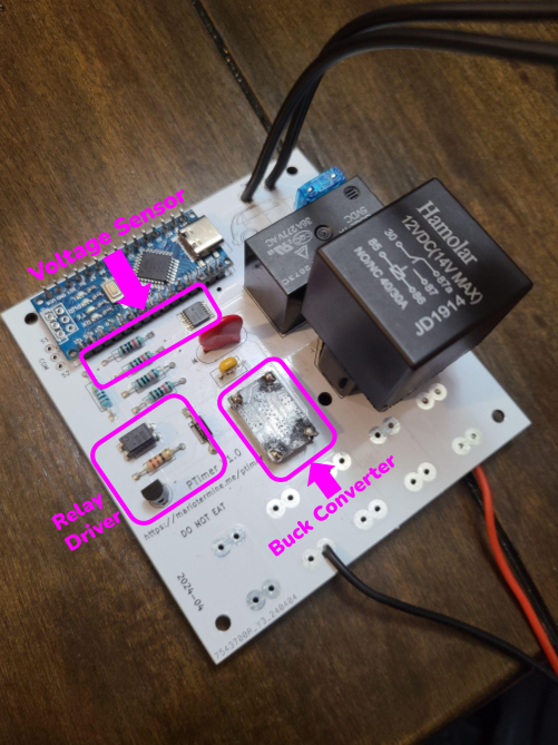
The board consists of 4 major systems.
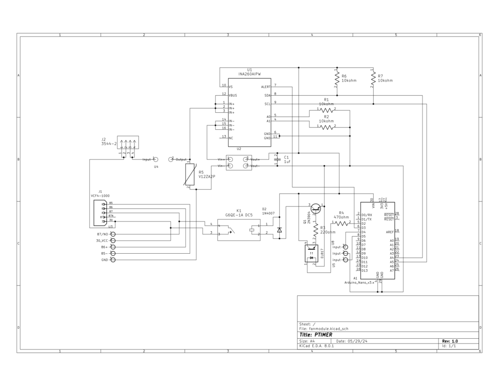
The first system is the microcontroller. Here, I used an Arduino Nano for its small footprint, low power consumption, and price. It has more than enough processing power for this project.
The second system is power. Since power electronics is not my expertise, and can be very complicated and unreliable if done incorrectly, I chose to utilize an off-the-shelf buck converter to convert 12v DC from the car into a stable 5v supply for the rest of the board. Even though cars are based on 12V systems, the voltage at the battery often varies significantly and property circuitry is needed for stable operation. Due to transient voltages that can occur during starting, a varistor was added across the buck converter’s inputs. Since the buck can only take in a maximum of 30V, the varistor works to protect it by converting any transient voltages above 16V into heat.
The next major system is the relay operation. This system utizlies 2 relays, one is the original relay from the vehicle and it operates exactly the same as it originally did. The microcontroller has no control of this relay, only the smaller through hole relay is able to be controlled. The board utilizes an optocoupler + transistor circuit to operate the relay.
The last major system of the board is the voltage sensing circuit. The INA260AIPW by TI is used here to sense the input voltage at the buck. The voltage value is used to detect when the vehicle is running, off, or low on charge. This allows the system to operate with its intended behavior and also shut off the fan if it detects the voltage of the battery is too low.
Software
The code for this board is pretty simple. After initizling all the components, it is simply a series of if/else statements to detect which state the vehicle is in (on or off) and then depending on other conditions such as the last time the board was enabled, the batteries state of charge, and others, it might choose to enable the fan which cools down the engine bay.
Check out the Github repo here
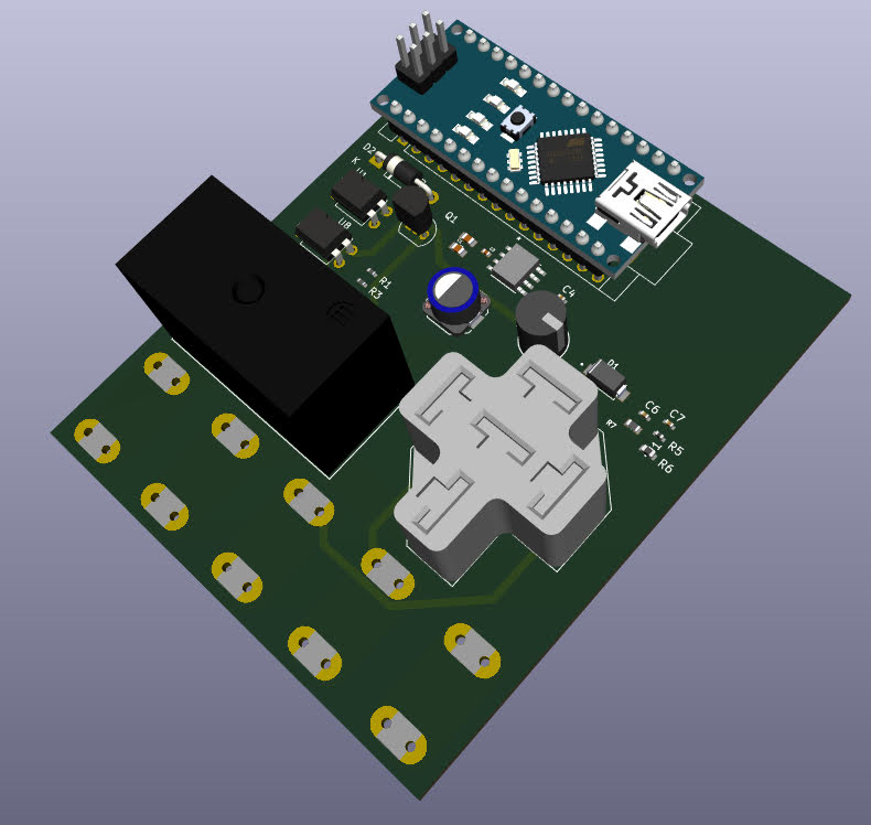
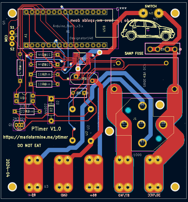
KiCad was used for the PCB design, and JLCPCB for the printing. There was plans to build a second, more refined version of this board and potentially sell the board and 3D printed bracket as a kit to other PT Cruiser enthusiasts, but I decided the board although very functional, was too expensive to reasonably sell. The components themselves are quite pricey, at nearly $40 per board, and it would also have to include soldering time, 3D printing time and materials, and some miscellaneous hardware and other components (like the device that plugs into the relay socket in the fuse box). If I were to create a second generation of the board, here are the improvements I would make:
– Fix power to buck input (missing trace)
– Fix wago footprint (wrong size footprint originally)
– Make power switch holes a little bigger (for easier soldering)
– Add headers for analog pins and power for expandability in the future (already added digital pins in v1)
– Re-organize Arduino code to operate more like a state machine for easier logic changes and variable updates
It’s interesting to note that while at idle (no relays being powered), the board only draws 7.5mA of power. This is quite nice to see considering no effort went into monitoring or reducing power usage via software. With this small of power draw, it should have nearly zero effect on the long term charge state of the car battery since most modern cars can draw upwards of 50-75mA while off.
